Abstract: The power signal acquisition system for CO2 gas shielded welding process was developed on a PC using Vualual C+ + 6.0. The use of multi-threading technology and double buffer technology solves the problem of data loss during high-speed data acquisition. Analysis results table: The developed system can accurately and completely collect the electricity signal during the welding process, and can intuitively analyze the stability of the welding process through the current-voltage probability density distribution and the droplet-transition short-circuit time frequency distribution, in order to further study the welding process. Quality monitoring lays the foundation.
Key words : CO 2 welding; signal acquisition; multi-threading; welding stability
0 Preface
The welding arc contains a wealth of information such as electricity, light, and sound, which can reflect various arc physical processes of arc welding. How to extract this information using modern sensing technology is the key to studying the welding process. Experts in the welding industry at home and abroad have developed a variety of sensors, including mechanical, arc, sound and vision types. Mechanical sensors are not flexible enough to use, and they are less suitable for use. The arc and the visual sensor have their own characteristics, and there are many researches at home and abroad. The arc sensor uses the arc's own current and voltage as the signal source, which is low in cost and good in accessibility. Therefore, it is widely used in the quality monitoring of welding process and automatic tracking of welds [1, 2, 5].
This article uses ADL IN K's PC I29112 multi-channel data acquisition card as the core, through V isual C+ + 6. 0 The program developed a power signal acquisition system on the PC, and analyzed the stability of the CO 2 gas protection short-circuit welding process, and laid the foundation for the study of welding process quality monitoring.
1 hardware composition
The signal acquisition system is shown in Figure 1. The system consists of a welding power source, a welding trolley, a PC, sensors, filters and a data acquisition card. The welding power source uses a silicon rectifier arc welder.
The welding current and voltage signals are respectively converted into voltage signals between 0 and 5 V by WB1221F Hall current sensor and WBV 121S linear isolation voltage divider of Mianyang Weibo Company, and filtered and sent to the input end of the signal acquisition card. The current sensor has an accuracy rating of 0.5 (within ±0.5% relative to full-scale output), a short response time (15 Ls), and a voltage sensor accuracy rating of zero. Level 2, response time is 5 Ls, high input impedance, low power consumption (400mW). They have the common feature of wide linear range (0-120% nominal input), strong overload capability, high isolation, low power consumption, and do not affect the welding loop parameters during measurement. Because the current sensor uses the principle of electromagnetic induction and Hall effect, its input and output are respectively different circuits, and the voltage sensing is separated by advanced linear diaphragm, so they are effectively isolated from the welding machine. The direct connection between the system and the weak system of the microcomputer protects the microcomputer and has a certain anti-interference effect on signal acquisition. The filter is an active low-pass filter with a passband cutoff frequency fc designed to be 500 Hz. The signal acquisition card is ADL IN K's PC I29112 multi-channel data acquisition card. The card features 16 single-ended inputs or 8 differential inputs. The A öD conversion time is 8 Ls, and the 12-bit input analog signal resolution. The accuracy is 0.01%. If only two signals are collected, the card can ensure accurate acquisition of signals at a maximum frequency of 55 kHz. According to the Shannon sampling theorem, the sampling frequency should be greater than 2 times the continuous signal frequency, and according to experience. The sampling frequency of the two channels is set to 4 kHz (fc×8); the 32-bit PC I bus, the bus controller AMCC2S5933 and the 8-word F IFO (F irst In F irst O ut ) cache, when it When working in DMA (D irect M emo ry A ccess) mode, data can be sent to the memory buffer at an extremely fast rate without taking up CPU time. And the driver of the card is provided in the form of DLL (Dynam ic L ink L ib rary), which facilitates visual programming.
Figure 1 Schematic diagram of the signal acquisition system
2 software design
Because high-speed data acquisition generally uses continuous acquisition mode, the driver transfers the collected data to the user buffer in turn. When the user buffer is full, the driver will overwrite the original buffer data, so if the original buffer data is not saved, it will be lost. In this paper, through the multi-threading technology of Windows XP system, combined with the data transfer mode of buffer half-full transfer data, this problem is solved by Visual C + + 6.0 programming [3.4]. The specific programming ideas are as follows.
Next page
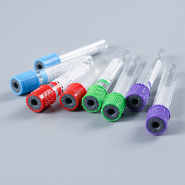
In the clinical medical experiments usinghuman venous blood as specimensome take the serum from the specimen as the experimental object.The blood collection tubes suitable for this type of medical tests are called serum blood collection tube.

color guide blood collection tubes,collection tubes for blood,tubes for blood collection,blood collection tubes color code
Yong Yue Medical Technology(Kunshan) Co.,Ltd , https://www.yonyuepcrtube.com