The modern residential structure has made the family life more and more closed, and the security issue is particularly important. The current security and alarm system is one of the most important ways to ensure the safety of homes and residents, and is also an important part of the digital home. In the event of an emergency such as a police, fire, or gas leak, it is necessary to complete the external police call in time by telephone.
This paper introduces a smart phone alarm system consisting of embedded alarm host and wireless sensor network node. The wireless sensor network technology is adopted to make the home security sensor form a wireless network; the dual-tone multi-frequency codec technology is used to realize active dialing, voice alarm and simple telephone control; and the embedded development platform with S3C2410 as the core processor is adopted. A new embedded alarm system with easy configuration, powerful functions and large coverage is constructed. 1 system hardware structure and working principle
1.1 System hardware structure
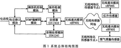
The system consists of an alarm host and a wireless sensor network node. Figure 1 is a schematic diagram of the overall structure of the system, the wireless communication module structure is identical. The control panel consists of a development platform and a wireless communication module based on the S3C2410 32-bit embedded microcontroller. The alarm host and the wireless sensor network node form a star topology wireless network.
 |
Using the IIS interface of the S3C2410 itself, the audio processing module [1] is constructed by extending the UDAl341, and the audio input of two channels and the audio output of one channel are realized. The alarm host exchanges audio data through the IIS interface, and the audio signal passes through the audio power. After amplification, the audio transformer is coupled into the telephone line to minimize the effects on the dual tone multi-frequency DTMF (DualTone Multi Frequency) signal.
The ringing detection module [2] firstly rectifies and filters the signal of the telephone line and sends it to the external interrupt input end of the S3C2410. The S3C2410 controls the telephone interface circuit according to different ring tone signals to realize different operations, and simultaneously recognizes the type and frequency of the signal. Provided to the upper application. When the hook control module receives the hook control signal from the CPU, the relay in the module connects or disconnects a 300Ω resistor to realize the automatic hook-up [3].
In this system, the DTMF codec circuit uses MT88L89 as the codec core device of DTMF signal. The DTMF signal generated by the remote user's telephone button is received by the MT88L89 and decoded by the DC capacitor of the coupling capacitor. After the end, the interrupt control terminal sends an interrupt signal to inform the CPU that the data is ready for reading. The MT88L89 outputs four. The bit parallel binary data is connected to the CPU through the Local Bus. At this time, the CPU can obtain the key value information; the CPU sequentially sends the telephone number to be dialed to the MT88L89 through the Local Bus, and converts to the DTMF signal through the MT88L89 to realize the dialing function.
1.2 How the system works
When a safety hazard such as a thief, fire, or gas leak occurs, the sensor transmits a digitally encoded alarm signal to the alarm host via the wireless sensor network. The alarm host immediately sounds a siren, and at the same time actively dials the user's preset telephone number to notify the user in the form of voice. The voice prompts the user to confirm receipt of the alarm information by means of a button, and the smart phone alarm recognizes the key value of the user button and determines the next action. The system also has a remote arming/disarming function, that is, after the owner authenticates, the system can be remotely controlled/disarmed by telephone. It has the function of being called to grab the line. When the user is in the house, the phone is busy, or someone calls in from outside to attempt to occupy the alarm line, the system will automatically grab the line alarm when the burglary occurs. 2 Wireless sensor network node design
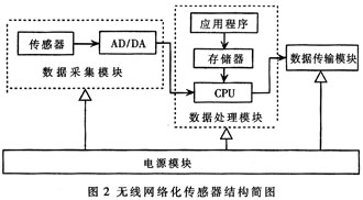
In different applications, the composition of wireless sensor network nodes is not the same, but generally consists of four parts: data acquisition, data processing, data transmission and power supply [4]. The form of the monitored physical signal determines the type of sensor. Processors usually use embedded CPUs, such as Motorola's 68HCl6, C51 series microcontrollers. The data transmission unit is mainly composed of a low-power, short-distance wireless communication module, such as the PTR8000 and ZigBee wireless module of the communication company. Figure 2 depicts the composition of a node where the direction of the solid arrow indicates the direction of flow of data in the node.
 |
2.1 processor
The AT89C2051 chip is selected as the processor of the wireless sensor network node. And use I / O port analog SPI port mode to communicate with nRF905, configuration memory interface also uses I / O port simulation.
2.2 Sensor
Responsible for home security, ensure that the area being monitored (balcony, doors and windows, aisles, vaults, etc.) is placed in sensitive areas of the sensor. There are many existing sensor products, such as infrared pyroelectric probes, microwave Doppler effect probes, microwave infrared multiplex probes, etc., which are used to detect thieves' intrusion. Ion smoke sensors and semiconductor gas sensors are used to monitor fire and gas leaks.
2.3 Wireless Communication Module
The peripheral MCU configures the PTR8000's internal registers and data transceiving via the SPI bus [5]. The PTR8000's SPI bus consists of four pins: CSN (SPl enable), SCK (SPI clock), MISO (master slave) and MOSI (master slave). Each operation of the SPI bus must begin on the falling edge of the enable pin CSN. CSN is active low and the data on the bus is active on the rising edge of the clock. The MCU operates on the SPI bus in two ways: read and write. In the read operation, CSN is first set low, and then a byte indicating the read command is output on the MOSI data line. At the same time, the PTR8000 outputs 1 byte of data indicating the status information on the MISO data line, and then Output a 1-byte address followed by valid data. It is relatively simple to perform a write operation. The MCU first pulls the CSN low, and then outputs the write command byte and the data byte on the MOSI line.
2.4 power supply
In this system, the nRF905 is a low-voltage device with a voltage requirement of 3.3V. To interface with it, the AT89C2051 also operates at 3.3V (AT89C2051 is a wide voltage device). The system is powered by a +5V supply and is converted to a 3.3V supply via an LT1117-3.3V conversion on the board.
3 design of the control panel
In this system, the control panel acts as a protocol conversion gateway between the public telephone network (PSTN) and the wireless sensor network. The hardware uses the core board of the Youlong FS2410, and the peripheral board is redesigned as needed. The FS2410 core board integrates ARM9 2410 processor, 64MB SDRAM, 64MB NAND FLASH, 2MB NOR FLASH and Ethernet controller, providing enough space for software development.
The peripheral board provides a 10M/100M Ethernet interface, three RS-232 serial ports, two USB ports, and one RJ11 interface. It expands a wireless communication module, a telephone alarm module and a power module. The Ethernet interface on the peripheral board can be directly connected to the Internet. The RS-232 serial port on the peripheral board is connected to the meta line transmission module PTR8000 through the MAX232.
The alarm host selects the ARM Linux operating system. Based on this, the embedded database SQLite is transplanted, and the smart phone alarm software is developed. It has the functions of active voice alarm, remote disarming/defending, and remote setting alarm call.
4 system software design
The entire system software design includes the software design of the wireless sensor network node (lower computer) and the alarm host system terminal (host computer). Due to limited space, only the data wireless communication strategy and the main program of the wireless sensor network node system are introduced here.
4.1 Data Communication Strategy between Host Computer and Lower Computer
In this system, the alarm host and each wireless sensor network node wirelessly transmit data. The communication protocol uses the frame format as shown in Table 1.
In Table 1, the leading characters can be 0xAA, 0xAA, 0xAA, 0xAA, 0xFF, 0x00, a total of 6 bytes, of which the first 4 bytes are the synchronization signal, the last 2 bytes are the frame start flag; the total length of the frame is not allowed. It will not exceed 256 bytes. If it is exceeded, it will be divided into multiple 256-byte frame transmission. The frame type field is used to define the frame format of the command and response. This field is 8 bits. The protocol frame is divided into initialization frame, confirmation frame, and data. Frame, control command frame and other types; address indicates the destination address of the data frame; checksum is CRCl6 check code.
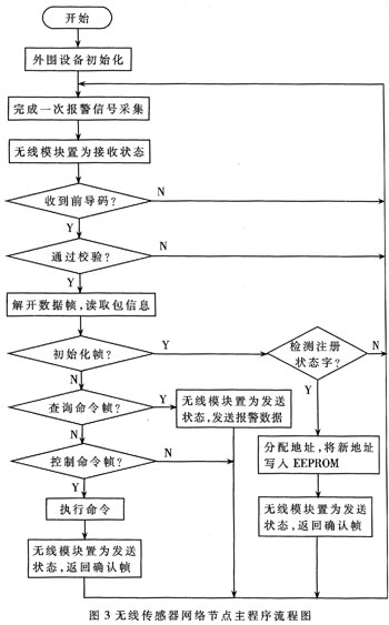
In the system, the wireless sensor network node and the alarm host form a single-hop star topology network. Each wireless sensor network node has a unique node number, which is assigned by the control panel and can be addressed by the alarm host. After the wireless sensor network node is powered on, it enters the standby state, and the alarm host sends the query command to the lower computer according to the above protocol. After the lower computer receives the data, it first judges the leading character to determine whether it is valid data, and then checks. After verification, it is judged whether the address is the local address; if yes, the packet is unpacked and the corresponding operation is performed; if it is a query command, the alarm information is encapsulated and returned to the alarm host according to the above protocol, otherwise the lower computer discards the data packet. After receiving the alarm protocol frame, the alarm host actively dials the preset telephone number and plays the alarm out through the voice. The control panel continues to query the lower computer in the same way until it finds the lower computer to be communicated. The entire network timing is uniformly controlled by the primary station, ensuring that there is no access violation.
4.2 Wireless sensor network node system programming
The wireless sensor network node system program is composed of a main program, a data collection subroutine, and a subroutine that communicates with the host computer. Here mainly introduces the design of the main program.
The main program is the core of the lower computer measurement and control system, which mainly completes the call to each subroutine, thus realizing the collection, storage and sending of data of the alarm data to the upper computer. When the lower computer receives the command sent by the host computer, it performs the corresponding operation according to the instruction. The main program flow chart is shown in Figure 3.
 |
The system adopts wireless sensor network technology to form a star-type topology wireless sensor network. When there is a smoke alarm or infrared alarm signal, it can actively dial the owner's phone, so that the owner can understand the safety hazard of the family at the first time. The user can also remotely set a new alarm telephone number and remote arming and disarming by telephone to achieve simple control of the alarm host. Increasing the control function of the system can realize remote telephone control of household electrical appliances, which will greatly promote the network, digitization and intelligentization process of the home.
references:
[1]. MT88L89 datasheet http://
[2]. PTR8000 datasheet http://
[3]. AT89C2051 datasheet http://
[4]. CSN datasheet http://
[5]. 100M datasheet http://
[6]. RS-232 datasheet http://
[7]. MAX232 datasheet http://
:
Surface conditioning non woven Sanding Belt
This product is made of high quality nylon nonwoven material and great aluminum oxide. It is applicable to handheld and automatic grinding apparatus,with elasticity and small grind,can be good to improve the grinding workpiece ,and easy to replace.
Compared with the traditional abrasives products,nylon abrasive belts have the following advantages: can control the minimum amount of grinding mil,.grinding depth anti-blocking,the minimum of tolerance probability,new abrasives grain continuously exposed in the grinding process,and good effect.
The non-woven, open web, durable construction is designed to resist loading and greatly increase the life of the Belt. Standard Abrasive Non-Woven Discs and Belts offer repeatable finishes for a wide variety of applications.
Application:
Providing additional strength and durability for removing paints,rust, corrosion, exit burrs, weld splatter, parting lines and deburring on ferrous and nonferrous metals.
Blending weld seams and deburring edges
We distributes and wholesales various brands of Abrasive Sanding Disc, Cutting Wheels , Abrasive Flap Disc , Flap Wheels , Flap Disc Backing Pad, Flap Disc Adhesive , Abrasive Machine and Surface Conditioning Product etc, and enjoy a high position among consumers.


abrasive sanding belt non woven,Nylon abrasive sanding belts,nonwoven sanding belt,non woven sanding belts,sanding belt for surface conditioning
Zhengzhou Jiading Abrasive Manufacturing Co.,Ltd , https://www.jiadingabrasive.com