Abstract: At present, people's demand for home fire prevention, anti-theft and remote control of household appliances is increasing. At the same time, mobile phones have become a communication tool for residents to carry around. Based on this, a GSM module-based remote control of household appliances through mobile phones is designed. An automatic SMS security alarm system that integrates fire and intrusion alarms. The system is controlled by AVR ATmega16 MCU external GSM module, with SMS with password operation, can set 8 groups of user phone numbers, can be Chinese SMS alarm, with infrared microwave double anti-theft and fire detection wireless communication interface, there are 2 ways Wireless control relay output, can be connected to power supply, video recording and so on. Finally, the actual measurement shows that the system has a good detection effect.
0 Preface
With the completion of a large number of modern residential quarters in China, there is an increasing demand for fire protection, anti-theft and remote power-off of household appliances. In the current society, mobile phones have become a daily communication tool for residents. This paper designs a security alarm system based on GSM module that can automatically send and receive Chinese alarm SMS to the owner by integrating fire and intrusion alarms for remote control of household appliances through mobile phones.
1 system structure
As shown in the schematic diagram of the GSM security alarm system, the system is controlled by the AVR ATmeg a16 MCU external GSM module. The host is operated by SMS with password. It can set 8 groups of user phone numbers, Chinese SMS alarm, and the system has 3 wireless channels. Detector (infrared microwave anti-theft, smoke alarm) Wireless communication interface, there are 2 channels of wireless control relay output, can be linked to power supply, video recording and so on. The three-way wireless detector consists of an infrared pyroelectric sensor, a microwave sensor, a smoke sensor, and a wireless transceiver module. The infrared pyroelectric sensor and the microwave sensor together constitute a microwave infrared composite intrusion detector, and the smoke sensor is mainly used for fire detection. Once the system is opened by the owner via SMS, if it is detected that someone has illegally invaded or a fire has occurred, the system will immediately send a text message to notify the owner of the user number (up to 8 mobile numbers). At the same time, in order to facilitate the master to leave the home to control the power on and off of the household appliances, the system also provides two wireless switches for remote control on and off, the user can control the remote wireless switch through SMS commands.
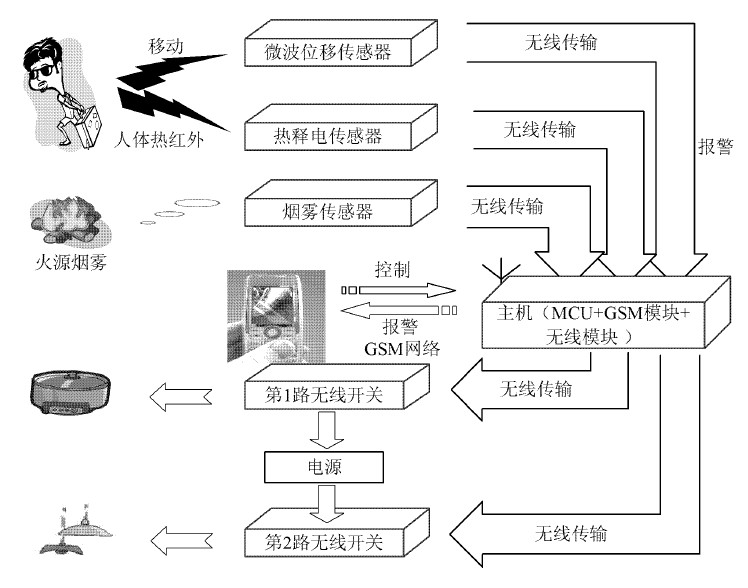
Figure 1 Schematic diagram of GSM security alarm system
As shown in the system host structure diagram of Figure 2, the system host is mainly composed of MCU (AT mega16 microcontroller), GSM (T C35i) and level conversion module, delay interface circuit (monostable trigger) and display module (12865LCD). 315 MH z transmit circuit, 315 MHz and 433 MHz receive circuits, and power adapter modules (AMS1117 3. 3 and KIS3RR3 buck modules).
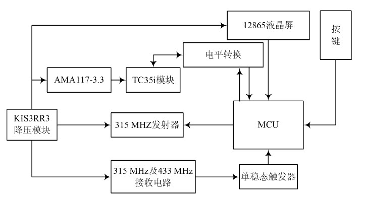
Figure 2 system host structure diagram
1. 1 GSM and level conversion module
The GSM module uses the Siemens industrial grade GSM module TC35i. Since the level of the T C35I UART is 2. 9 VT TL level, it cannot be directly connected to the AT mega16, so as shown in the level conversion circuit of Figure 3, it is used on the RXD side. Two simple non-gate level shifts and one current-limiting resistor at the T XD end. Since the TC35I requires a high power supply (the voltage drops more than 400 mV will be reset), and the current peak value will reach 2.5 A during the data transmission, a large-capacity electrolytic capacitor of 3 300 uF is connected in parallel with the T C35I to Reduce the need for power.
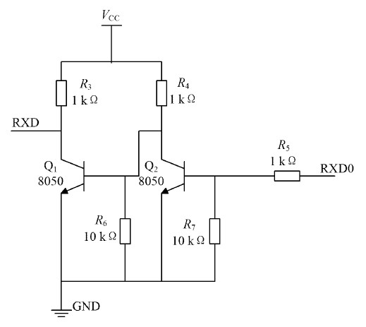
Figure 3 level conversion circuit
1. 2 delay interface circuit and display module
The system receives the external wireless signal by means of inquiry. In order to prevent signal loss and try to be compatible with the same coded wireless module on the market, this paper designs a monostable delay interface circuit. The schematic diagram of the circuit is shown in the figure. As shown in Figure 4, when the Q1 base is at a high level, the amount of power saved by C2 is released, and the comparator output is high. When the base is lowered from high level to low level, C2 is charged through R3, and the comparator's inverting terminal potential Slowly rising, once the voltage of C2 is higher than V ref , the comparator flips and outputs a low level, thus achieving the purpose of delay.
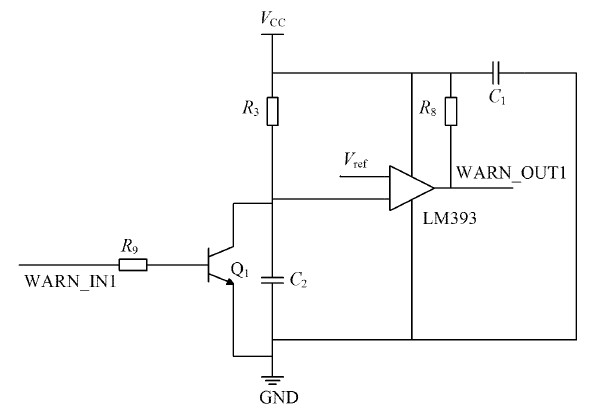
Figure 4 monostable trigger delay interface circuit
The display part consists of the ST7920LCD, and the LCD and MCU are connected using SPI. The LCD backlight is triggered when a button is pressed. Due to the low probability of the burglar alarm, smoke alarm, and SMS remote control being triggered at the same time, the entire system does not have to use too many frequency points for communication. The host uses a 315 MHz wireless module to control the wireless switch, and the heat release The electric infrared and microwave displacement sensors use two different frequencies of 315 MHz and 433 MHz to send alarm signals to the host respectively, so that the alarms do not interfere with each other. The smoke sensor sends a signal to the host using a frequency of 315 MHz.
1. 3 host wireless transceiver module
The wireless transceiver module is mainly composed of a wireless coding chip SC2262, a wireless decoding chip PT2272, a 315 MHz transmission module, and a receiving module. When the host controls the wireless switch, the wireless code chip SC2262 is used, the address setting is consistent with the receiving part PT2272, and the oscillating resistance should be matched. When the MCU is powered on or the host receives the remote control message, the MCU firstly stores the wireless switch according to the EEPROM. The state changes the PD4~PD7 level, then the MCU will send a low level pulse of 1 s to the 16 pin (TE) of the PT2262, so that the SC2262 encodes the data of PD4 ~ PD7 and outputs it from the 17 pin to the 315 MHz. Transmitter module.
Since the wireless transmitting module of some detecting sensors on the market only triggers a high level "1", the host decoding chip cannot use the PT 2272L4 with latch. Otherwise, the data output by PT 2272L4 is always high, and will always be generated. False positives, so in order to better be compatible with the market products, the wireless receiving part of the system adopts the non-latching PT2272M4 chip to connect with the 315 MH z and 433 MHz receiving modules respectively.
In this way, when someone invades and triggers an alarm, the signals sent by the two alarms will not interfere with each other because they are on the same frequency, resulting in decoding errors, which avoids the detection of someone invading but the host has no alarm. The smoke alarm receiver and the microwave alarm use the same PT2272 M4 and receiver module. Since the signals emitted by the infrared, microwave, and smoke alarms are discontinuous and asynchronous, the received signal will be 3 s high level by the 3-way monoflop, which improves the accuracy of the MCU sampling judgment.
2 system software process
The software flow chart of the system is shown in Figure 5.
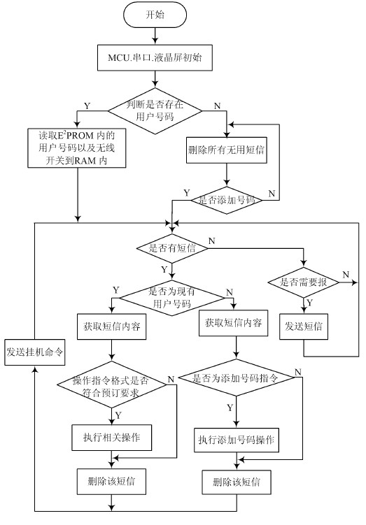
Figure 5 software flow chart
3 system test
The microwave sensor and infrared sensor are mounted on the wall and the installation height is 3~5 m. The infrared sensor is tested from three different angles, which are positive, 30°C to the right and 45°C to the right. The effective sensing distances are shown in Figure 6, A, B and C. The microwave sensor is tested from three different angles, which are positive, 30°C to the right and 135°C to the right. The effective sensing distance is shown in A, B and C in Figure 7. The maximum inductive linear distance of the infrared sensor is 7 m, the optimum distance is 6 m, and the sensing angle is 90 °C. The maximum inductive linear distance of the microwave sensor is 9 m, and the near-distance is omnidirectional. The optimal distance is 5 m.
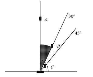
Figure 6 Schematic diagram of infrared sensor sensing distance test
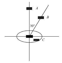
Figure 7 Schematic diagram of microwave sensor distance sensing test
4 Conclusion
The automatic SMS security alarm system designed in this paper adopts pyroelectric infrared and microwave dual sensors, which greatly reduces false alarms and false negatives, and improves the reliability of security alarm system applications. The external GSM module of AVR ATmeg a16 MCU is used as the control host. As long as it is within the GSM network, it can remotely alarm regardless of the user's location. The operation with SMS with password increases the security of the system. 8 groups of users can be set. Phone number, can be Chinese SMS alarm; With infrared microwave double anti-theft wireless communication interface, providing remote wireless switch function, there are 2 wireless control relay output terminals, can be linked to power supply, video recording and so on. The design of this paper has improved the performance of security products while reducing the cost of the system.
references:
[1]. SC2262 datasheet http://
[2]. PT2272 datasheet http://
[3]. PD4 datasheet http://
[4]. PT2262 datasheet http://+_1071334.html.
[5]. PT2272M4 datasheet http://
With eye-catching colors and a natural wood look, this mosaic is perfect for your next home renovation! High-quality recycled glass transforms your home into a magnificent space.
Wood Mosaic Printing is our another printing glass mosaics, and it is very popular as well. It is same as other pattern printing mosaics, made of recycled glass powder, under the high temperature, the color and the pattern become solid and not easy to fade away.
Use wood-looking recycled glass tiles to update your space and bring a natural wood feeling with a nonporous surface. This wood Recycled Glass Mosaic Tiles allows you to have the beauty of wood-look tiles with an easy-to-clean glass surface, and thanks to the use of recycled glass, is a great way to incorporate eco-friendly and sustainable building materials into your home! While it gives a clean backdrop for your home design to shine, it allows other design elements to take center stage.Glass mosaics can be used anywhere since they are easy to clean and stain-resistant. This makes glass tiles highly preferable especially for high moisture areas. Whether you choose to have them on your floors, walls or use as a fireplace surround, these tiles have both the aesthetic appeal and ease of use you`re looking for.
Hexagon Wood Tiles,Wood Look Hexagon Tile,Wood Mosaic Printing Tile,Wood Lantern Printing Recycled Glass Tile
C&K MOSAIC , https://www.cnkmosaics.com