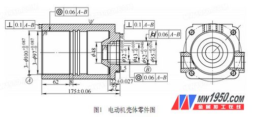
Among the products I produced, the motor structure is quite typical, and the processing of the motor casing is difficult. The motor housing is made of 1Cr18Ni9Ti material, which requires high dimensional accuracy, shape accuracy and surface roughness, as shown in Figure 1. In order to achieve fast clamping and precise positioning in small batch production, we have designed special fixtures for turning high-precision holes at both ends to ensure the accuracy of the shape and position of the holes at both ends.

1. Process analysis of parts
Processing difficulties in that the part turning inner bore ends, the hole left and right φ100 +0.087 0 mm bore φ32 +0.039 0 mm, φ52 +0.046 0 mm, not only the dimensional precision, high surface roughness Moreover, it is required to use the central axis of the two holes as a reference, and the coaxiality error of the left and right end holes does not exceed 0.06 mm, which is difficult to process. In order to ensure the accuracy of the shape and position, in the process design, the positioning reference must be correctly selected and the processing sequence should be arranged reasonably.
According to the principle of uniformity of the reference, the positioning reference should be selected as much as possible with the design basis. Therefore, when the part is machined, the inner hole is selected as the positioning reference, and the inner hole of the left end is first processed to be φ100 +0.087 0 mm, and then the hole is positioned, and the head is clamped. The process plan of processing the left end of each hole to the size. In this process scheme, the key to the implementation is the positioning and clamping method of the left end inner hole φ100 +0.087 0 mm.
2. Design and use of fixtures
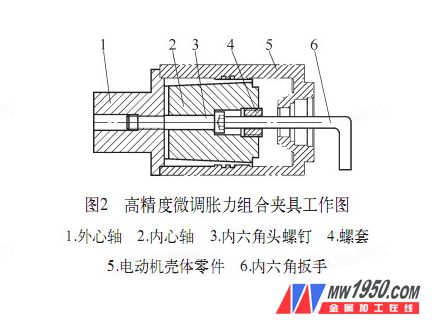
Because the product is processed in small batches, the fixture must be designed to be quickly clamped, accurately positioned, and reused. Through the above analysis, we designed a high-precision fine-tuning expansion force fixture, as shown in Figure 2.

The working principle of the set of clamps is that the outer ring of the right outer shaft 1 is gap-fitted with the inner hole of the left end of the motor housing part 5, and eight 0.5-1 mm wide are cut in the axial direction of the external mandrel 1 corresponding to the outer circle. The groove is formed at the same time, and the inner hole is designed as an inner tapered surface with a slope of 2.5°, which forms a fit with the outer tapered surface of the inner mandrel 2. Under the condition that the inner hole of the left end of the motor housing part 5 has been finished and the inner hole of the right end has been turned by the pre-hole, when the clamp is used, the left outer end of the outer mandrel 1 is mounted in the lathe chuck, and the inner mandrel 2 passes through the inner hexagon head. The screw 3 is coupled with the outer mandrel 1, and then the inner hole of the left end of the motor housing part 5 is inserted, and then the hexagonal head screw 3 is tightened by the hexagonal wrench 6, pushing the inner mandrel 2 to the left, and the inner mandrel 2 is The outer tapered surface expands the inner tapered surface of the outer mandrel 1, so that the outer circular shaft of the outer mandrel 1 with 8 grooves is elastically deformed, and is expanded outward, and the motor casing part 5 is fixed. For the same reason, the hexagon socket head cap screw 3 is loosened by the hexagonal wrench 6, and the outer mandrel 1 is elastically restored, and the motor case part 5 can be removed.
In addition, after the clamp is used, in order to facilitate the smooth disengagement of the inner and outer mandrels, a screw sleeve 4 is also designed. As shown in FIG. 3, two φ4 mm holes of the screw sleeve end face can be utilized, and the inner shaft is passed through the trigger rod. Rotate and then pull out.

3. Precautions
In the fixture, the production of the outer mandrel is more critical, and the following points should be noted:
(1) The outer circles at the left and right ends should be coaxial, preferably formed by a single clamping cart.
(2) The outer ring size and accuracy of the right end should be controlled well. It can be matched with the clearance of the inner hole of the motor housing part as H9/h8. At the same time, the surface roughness value Ra=1.6μm.
(3) In order to make it elastically deformed, the design of the wall thickness is very important, and the wall thickness (at the large end of the tapered surface) can be about 3 mm. At the same time, the selection of materials and heat treatment are also very important. The materials above medium carbon steel can be selected and quenched and tempered to improve elasticity and wear resistance.
4. Conclusion
This set of fixtures uses the principle of elastic collet and expansion mandrel to subtly complete the secondary clamping turning of high-precision coaxial holes. After small batch production, it is detected by the coordinate measuring machine. The axial error does not exceed 0.03mm, exceeding the design requirements, achieving fast clamping and precise positioning, improving production efficiency and product quality.
The fixture structure can also be extended to the secondary clamping processing of high-precision coaxial holes of similar sleeve parts, and has good practicability and economy in a small batch production mode.
Gabions & Reno Mattresses are rectangular baskets made of heavily galvanized, double twisted, steel Woven Wire Mesh. The single unit constructed baskets are assembled, laced together and then filled with stone to form a monolithic structure. Gabions and Reno mattresses are used for retaining walls, sound barriers, channel linings, slope stabilization, dams and weirs. They are particularly effective in restoring the environment and promoting vegetation growth.
Gabion Mesh,Gabion Wire Mesh,Galvanized Gabion Mesh,Gabion Basket Mesh,Pvc Coated Gabion Mesh
Anping Sanxing Wire Mesh Factory , https://www.sanxingwiremesh.com