1 Scope
This standard specifies the terms and definitions, classification and nomenclature, conditions of use, requirements, test methods, inspection rules, signs, packaging, transportation and storage of solar photovoltaic lighting fixtures.
This standard applies to the use of solar photovoltaic batteries to generate electricity at rated voltages of 24V and below. The charge and discharge controllers charge and store energy for the batteries, and then the batteries discharge to light the DC lighting fixtures.
2 normative references
The clauses in the following documents have been adopted as references to this standard. For dated references, all subsequent amendments (not including errata content) or revisions do not apply to this standard, however, encourage the parties to reach an agreement based on this standard to study whether the latest version of these documents can be used . For undated references, the latest version is applicable to this standard.
GB/T 191 packaging and transportation icon standard
QB/T 1553 lamp corrugated carton packaging technical conditions
GB/T 2423.1-2008 Environmental testing for electric and electronic products Part 2: Test methods Test A: Low temperature
GB/T 2423.2 Environmental testing for electric and electronic products Part 2: Test methods Test B: High temperature
GB/T 2423.3 Environmental testing for electric and electronic products Part 2: Test methods Test Cab: Constant damp heat test
GB 7000.1-2007 Luminaires Part 1: General requirements and tests
GB 7000.5-2005 road and street lighting safety requirements
GB 9969.1 instruction manual for industrial products
Self-ballasted fluorescent lamp performance requirements for GB/T 17263 general lighting
3 Terms and Definitions
The following terms and definitions apply to this standard.
3.1
Solar photovoltaic lighting PV lighting luminaire
The solar system is composed of solar modules, batteries, controllers, and electric light sources. It uses solar energy as an energy source and is used as an off-grid, stand-alone lighting system.
3.2
Solar module photovoltaic modules
The smallest non-separate solar cell combination device with package and internal connection that can provide DC output separately.
3.3
Light control
The use of solar battery voltage characteristics in the weak light and strong light changes as a trigger signal to control the lighting switch.
3.4
Time control
Timing control of lighting switch method.
3.5
Charge and discharge controllers
A device that controls the charge and discharge of the battery and protects it.
3.6
Battery battery
Used to store energy storage cells that convert solar energy into electrical energy from solar photovoltaic cells.
4 Classification and Naming
4.1 Classification
According to its application, products are divided into street lamps, garden lamps, landscape lamps, lawn lamps and underground lamps.
4.2 Model Name
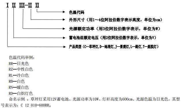
Model specifications are named as follows:
5 conditions of use
5.1 Ambient temperature of street light, garden light, landscape light, lawn light and underground light: -10°C~60°C;
5.2 Relative humidity of street lights, garden lights and landscape lights: 0 to 90% RH; relative humidity of lawn and underground lights: 0 to 98% RH;
5.3 Sites without corrosive and destructive substances.
6 requirements
6.1 Appearance
6.1.1 The shell surface is firmly plated and the paint surface is well-proportioned, with no flaking, rust and cracks.
6.1.2 The enclosure panel is flat and all the signs, marks, and texts meet the requirements. The functions are displayed clearly and correctly.
6.2 Structure
6.2.1 Luminaires containing replaceable parts or components should have sufficient space to allow these parts or components to be replaced safely and easily.
6.2.2 The trough should be smooth, without sharp edges, burrs and burrs.
6.2.3 The components should be complete and complete without any defects affecting performance. All parts should be firmly installed without looseness. Metal parts should be corrosion resistant or treated with a suitable corrosion resistant coating. Each connector should be protected against loosening due to vibration or the like.
6.2.4 The power terminals shall be positioned or protected by a method such that if there is a conductor in the stranded conductor after unplugging from the terminals, there is no danger of the live parts coming into contact with the metal parts. The metal part is the lamp fully assembled. After use with the standard test finger accessible.
6.2.5 Insulation bushings shall be provided at the connection points and joints of the internal wiring. The insulation performance of the insulation bushings shall not be lower than the insulation performance of the insulated conductors, and shall be designed as switches, lamp holders, terminal blocks, wires or the like. After they are installed, they can still be reliably held in their original positions.
6.2.6 External Wiring and Internal Wiring
6.2.6.1 Fixtures Providing non-removable flexible cables or cords, or those designed for the use of non-removable flexible cords or cords, shall be provided with cord holders to protect the conductors connected to the terminals from stress, including twisting. And prevent the protective layer from being worn out. The effect of stress relief and twist prevention should be obvious.
6.2.6.2 External flexible cables or cords Pass through the hard material cable entrance, the cable entrance should have a smooth round edge, the minimum radius of the round edge is 0.5mm.
6.2.6.3 The internal wiring shall be properly positioned or protected so that it will not be damaged by acute angles, rivets, screws, and similar parts, or it may be damaged by moving parts of switches, joints, lifts, bellows, and similar parts. The wiring must not be along the cable. The vertical axis is twisted more than 360°.
6.3 Dust and Waterproof
The degree of protection of the lamps should not be lower than IP53, and the protection level of the control box should not be lower than IPX3.
6.4 Wind protection
The overall luminaire (including pole) should have sufficient strength and should meet the requirements of 6.3 of GB 7000.5-2005.
6.5 Anti-theft
All parts should have anti-theft measures and special tools should be used for disassembly.
6.6 Security Performance
6.6.1 Clearance and Creepage Distance
Clearance is not less than 3.2mm, creepage distance not less than 3.2mm.
6.6.2 Insulation Resistance and Electrical Strength
6.6.2.1 Insulation resistance
The insulation resistance between metal parts and terminal blocks, between live parts and lamp housing, and between live parts with different polarity shall not be less than 2MΩ.
6.6.2.2 Electric strength
Between the metal components and the terminals, between the live parts and the lamp housing, between the live parts of different polarities should withstand the frequency test voltage 500V 1min (leakage current ≤ 20mA), no arcing or breakdown .
6.6.3 Lightning Protection
Street lights, garden lights, and landscape lightings should have lightning-protected grounding bolts as a whole and be reliably grounded to prevent lightning strikes.
6.7 Environmental Performance
6.7.1 Low temperature test
The charge-discharge controller shall be able to work normally after conducting the low-temperature test according to the standard of GB/T 2423.1 and meet the requirements of 6.8.4 or 6.8.5.
6.7.2 High temperature test
The charge-discharge controller shall be able to work normally after conducting the high-temperature test according to the standard of GB/T 2423.1 and meet the requirements of 6.8.4 or 6.8.5.
6.7.3 Constant Humidity Test
The charge-discharge controller shall be able to work normally after a constant damp heat test according to the standard GB/T 2423.1 and meet the requirements of 6.8.4 or 6.8.5.
6.8 Using Performance
6.8.1 Voltage
The rated voltage of the sealed lead-acid battery pack and the fully charged voltage shall comply with Table 1.

6.8.2 luminous efficiency of electric light source
At rated input voltage, the light effect is not less than 40lm/W.
6.8.3 Power Deviation of Electric Light Source
The difference between the actual consumed power and the rated power shall not exceed 15% at the rated input voltage.
6.8.4 Light control function
The light control function of the lamp should be normal. When the light intensity drops to the starting point, the lamp should be able to automatically light up within ±5% of the set start value; when there is sunlight and the light intensity rises to the start point, ±5% of the start value is set. Inside, the luminaire should be extinguished automatically.
6.8.5 Time Control Function
The time control function of the lamp should be normal. According to the set time, the time error of the lamp lighting and extinguishing should be less than 10min.
6.8.6 Charge and discharge performance
Under good lighting conditions, after the system is fully charged, street lights, garden lights, landscape lights, and buried lights should be guaranteed to light up for 3 to 5 consecutive rainy days. The minimum lighting time per day should be no less than 10 hours. The lawn light should be guaranteed. It can light up for 3 to 5 consecutive rainy days, and the minimum lighting time per day is not less than 6 hours.
6.8.7 Protection Features
6.8.7.1 should have a charge and discharge controller input, output short circuit protection circuit;
6.8.7.2 should have a load, solar cell module or battery reverse polarity protection circuit;
6.8.7.3 should have a protection circuit to prevent the battery reverse discharge of solar modules;
6.8.7.4 There shall be a breakdown protection circuit caused by a lightning strike in a multi-landmine area;
6.8.7.5 should have the function of the battery full disconnect (HVD) and undervoltage disconnect (LVD).
6.8.7.5.1 Full Disconnect and Restore Function
See Table 2 for HVD and recovery voltage values ​​for sealed lead-acid batteries.

6.8.7.5.2 Undervoltage Disconnect and Resume Functions
When the average voltage of the monomeric lead-acid battery drops to the over-discharge point (1.80±0.05)V/only), the controller shall be able to automatically cut off the load; when the voltage rises to the charge recovery point (2.20-2.25)V/only), The controller should be able to automatically or manually restore power to the load
Note 1: The rated voltage of the monomer lead-acid battery is 2V;
Note 2: Other types of batteries refer to their product specifications.
6.8.8 No-load loss (quiescent current)
The maximum power consumption of the controller must not exceed 1% of its rated power.
6.8.9 Charge and discharge loop pressure drop
When charging or discharging, the voltage drop through the controller must not exceed 5% of the system's rated voltage.
6.8.10 Impact Voltage
The controller can sustain an impact higher than 1.25 times the nominal open circuit voltage of the solar module for 1 hour.
6.8.11 Inrush Current
The controller can sustain an impact higher than 1.25 times the nominal short-circuit current of the solar module for 1 hour.
6.8.12 Temperature rise
The temperature rise of any accessible part of the luminaire must not exceed 65K during the lamp start-up period, during the stabilization period and after stabilization.
7 test methods
7.1 Appearance
Visual inspection should meet the requirements of 6.1.
7.2 Structure
Visual inspection and operational inspections should meet the requirements of 6.2.
7.3 Dust and Waterproof
According to the 9.2 test of GB 7000.1-2007, it should meet the requirements of 6.3.
7.4 Wind protection
According to the 6.3 test of GB 7000.5-2005, the requirements of 6.4 shall be met.
7.5 Anti-theft
Visual inspection and operational inspections should meet the requirements of 6.5.
7.6 Security Performance
7.6.1 Clearance and Creepage Distance
The use of plug gauges or vernier calipers should meet the requirements of 6.6.1.
7.6.2 Insulation Resistance and Electrical Strength
According to the test of 10.2 of GB 7000.1-2007, the requirements of 6.6.2 shall be met.
7.6.3 Lightning Protection
Visually inspect the type and rating of the arrester to ensure that the expected impact energy is absorbed. Visual and operational inspections should meet the requirements of 6.6.3.
7.7 Environmental Performance
7.7.1 Low temperature test
According to GB/T 2423.1 standard "test Ab". The test temperature is (-10 ± 3) °C. When the power is applied and the rated load is maintained for 2 hours, the controller should be able to work normally and meet the requirements of 6.7.1.
7.7.2 High temperature test
According to GB/T 2423.2 standard "test Bb". The test temperature is (60 ± 2) °C. The power is applied and the rated load is maintained for 2 hours. The controller should be able to work normally and meet the requirements of 6.7.2.
7.7.3 Constant Humidity Test
According to GB/T 2423.3 standard "test Cab". The test temperature is (40±2)°C and the relative humidity is (93±3)%RH. For 48h, the controller should work normally and meet the requirements of 6.7.3.
7.8 Using Performance
7.8.1 Voltage
Measuring the voltage of each point with a digital voltmeter with an error of no more than 1% shall meet the requirements of 6.8.1.
7.8.2 luminous efficiency of electric light source
Measured according to the method specified in 6.4 of GB/T 17263, shall meet the requirements of 6.8.2.
7.8.3 Power Deviation of Electric Light Source
Measure the power deviation of the light source with a digital multimeter with an error of no more than 1% and meet the requirements of 6.8.3.
7.8.4 Light Control Features
Light control "open function" simulation: In the daytime, after the lamps are connected according to the electrical circuit diagram, the light-receiving material can completely block the light-receiving surface of the solar module, and then according to the delay time on the instructions, after observing the corresponding time, the light can No automatically lights up. If it is on, it means that the light control "ON function" is normal; if it cannot light, it means that the light control "ON function" is invalid.
Light control "off function" simulation: In the daytime, according to the above operation, remove the shielding on the solar cell module and observe whether the light can automatically extinguish. If it can be extinguished, it means that the light control “off function†is normal.
7.8.5 Time Control Function
Set the time control, observe the lighting and extinguishing of the lamp, and press the timer to set the time, which should meet the requirements of 6.8.5.
7.8.6 Charge and discharge performance
Under good lighting conditions, the lighting system is set to work, and the charge and discharge performance of the lighting should meet the requirements of 6.8.6.
7.8.7 Protection Features
7.8.7.1 Input and Output Short Circuit Protection
Check whether the controller has input and output short-circuit protection circuits. Short-term short-circuiting of the input and output respectively should be able to work normally, meeting the requirements of 6.8.4 or 6.8.5.
7.8.7.2 Reverse polarity protection;
After the DC stabilized power supply, which will be adjusted to the rated voltage, is connected to the controller's solar energy and the input of the battery for a short period of time, the controller shall be able to operate normally and meet the requirements of 6.8.4 or 6.8.5.
After the lamps are connected according to the electrical circuit diagram and the load is reversed for a short time, the controller should work normally and meet the requirements of 6.8.4 or 6.8.5.
7.8.7.3 Reverse discharge protection
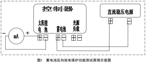
The test circuit is shown in Figure 1. The ammeter is added between the positive and negative terminals of the solar cell module of the controller, and the voltage of the DC stabilized power supply connected to the battery terminal is adjusted to reach the rated voltage, and the milliampere meter reading is read. If the current is less than 1mA, there is reverse discharge protection.
7.8.7.4 Lightning Protection
Visually check the type and rating of the arrester to ensure that the expected impact energy is absorbed.
7.8.7.5 Battery Full Disconnect (HVD) and Undervoltage Disconnect (LVD) Functions
7.8.7.5.1 Full Disconnect and Restore Function
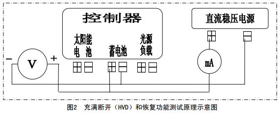
Test circuit shown in Figure 2. Connect the DC stabilized power supply to the battery input of the controller, and insert the current meter into the battery input loop of the controller to simulate the voltage of the battery and adjust the voltage of the DC stabilized power supply to reach the HVD point. The device should be able to disconnect the charging circuit; reduce the voltage to restore the charge point, and the controller should be able to reconnect the charging circuit.
7.8.7.5.2 Undervoltage Disconnect and Resume Functions
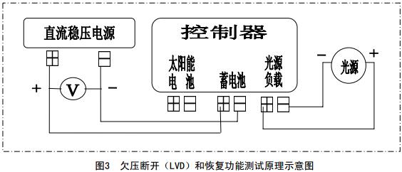
The test circuit is shown in Figure 3. Connect the DC stabilized power supply to the battery input of the controller, simulate the voltage of the battery, connect the lamp to the load end of the controller, and then adjust the voltage to the overdischarge point. At this time, the controller should be able to automatically disconnect the load; To the charge recovery point, the controller should be able to turn on the load again.
7.8.8 No-load loss (quiescent current)
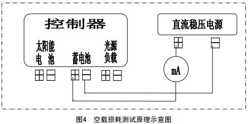
Test circuit shown in Figure 4, disconnect the controller's charge input and load output, the DC power supply is connected to the controller's battery terminal, and the current meter is serially connected to the controller's battery input loop, measure the controller's input current Calculate the power consumption value according to the rated voltage and meet the requirements of 6.8.8.
7.8.9 Charge and discharge loop pressure drop
7.8.9.1 The DC power supply is connected to the controller solar cell module input, adjust the DC power supply to make the charging loop current to the rated value, using a voltmeter to measure the voltage drop of the controller charging circuit, shall comply with this standard 6.8. 9 requirements.
7.8.9.2 Connect the DC stabilized power supply to the input terminal of the controller battery, adjust the DC stabilized power supply so that the discharge loop current reaches the rated value, and use a voltmeter to measure the voltage drop of the controller discharge loop, which shall meet the requirements of 6.8.9 of this standard. .
7.8.10 Impact Voltage
The DC stabilized power supply is connected to the input end of the controller solar cell module, and the DC stabilized power supply voltage is adjusted to 1.25 times the nominal open circuit voltage of the solar cell module. After continuing for 1 hour, the controller should be able to work normally and comply with the standard 6.8 .10 requirements.
7.8.11 Inrush Current
Connect the DC stabilized power supply to the input of the controller solar cell module, the variable resistor to the controller battery input, and adjust the variable resistor so that the charging loop current reaches 1.25 times the nominal short-circuit current of the solar cell module for 1 hour. After that, the controller should work properly and meet the requirements of 6.8.11 of this standard.
7.8.12 Temperature rise
The test is performed when the lamp is operating normally. Measured with a digital temperature meter and attached a thermocouple to any point on the surface of any accessible part of the lamp. After the temperature rise is stable at the measured point, the measured value is read. The maximum temperature rise should meet the requirements of 6.8.12.
8 inspection rules
8.1 Inspection Classification
Inspection is divided into type inspection and factory inspection.
8.2 type inspection
8.2.1 When one of the following conditions is met, a type inspection shall be carried out. The type inspection sample must be a product that has passed the factory inspection.
a) Stereotype testing before formal production;
b) changes in product structure, main raw materials or production processes may affect the quality of the lamps;
c) Stop production for more than one year and re-production;
d) During normal production, once every year;
e) When a major quality accident occurs;
Sampling luminaires should be randomly selected in the same model of production.
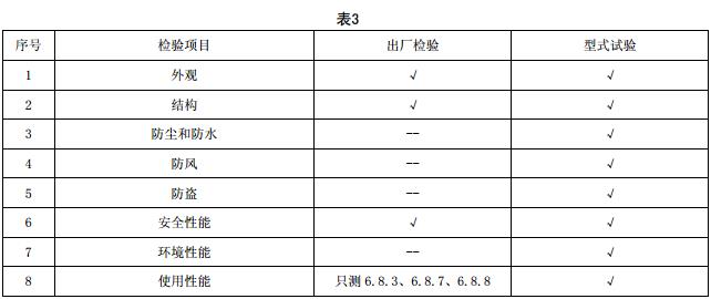
8.2.2 The test items, sample quantity and test procedure for type inspection are shown in Table 3.
8.2.3 Sampling and Determination
The sampled luminaires shall randomly select two samples from the factory inspection products of the same type manufactured to be used as samples, one for inspection and one for sample preparation. If all tests are qualified, the product is judged to be qualified; if a nonconformity is found in the inspection, retesting is allowed on the prepared sample. If the retested item is still unqualified, the product is judged as unqualified.
8.3 factory inspection
Each product must be inspected by the manufacturer's quality inspection department with a certificate before leaving the factory.
8.3.1 Inspection items
The factory test items and test procedures are shown in Table 3.
8.3.2 Determination
Products should be tested in accordance with all the items specified in Table 3, and can be delivered only after passing inspection.
9 signs, packaging, transportation and storage
9.1 mark
9.1.1 Product Logo
The product should have at least the following signs, and the sign should be clear and firm:
a) Product Name
b) Source mark (may take the form of a trade mark, manufacturer, or vendor name).
c) Model
d) Rated voltage
e) Rated power
f) Implementation of standards
g) Certificate of conformity
The product packaging should have a certificate of conformity, and the certificate of conformity should indicate:
a) Name of manufacturer
b) Product name and model
c) Date of manufacture: year, month, day
d) Inspection of employee number or inspection seal
e) Implementation of standards
9.2 Packaging
Product packaging should have at least the following symbols
a) Manufacturer's name or trademark and manufacturer's address
b) Product name and model
c) Rated voltage and rated power
d) Precautions such as careful handling
e) Implementation of standards
9.3 Transportation
The packaged product can be transported by any means of transport. In the process of transportation, the sun, rain, and strong vibrations should be prevented.
9.4 Storage
Products should be stored in a dry, ventilated, leveling room. Do not contact with water, oil, or corrosive materials.
Bathroom Cabinets,Wood Color Bathroom Cabinet,Solid Wood Bathroom Cabinet,Bathroom Cabinet
PRO CABINET SOLUTION PTY LTD , https://www.pcscabinet.com.au