CNC programming has gone through three stages of manual programming, APT language programming and interactive graphics programming. Because interactive graphics programming has the characteristics of high speed, high precision, good intuitiveness, easy inspection and maintenance, it has become the NC programming method commonly used in advanced CAD/CAM software at home and abroad. This article focuses on process processing issues in interactive graphics programming, and uses this knowledge to program the legend using PROE/CAM.
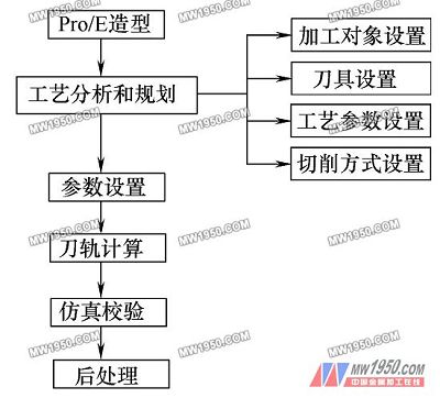
Since the implementation of interactive graphics programming is based on CAD technology, as long as we create a 3D solid model through Pro/E, PROE/CAM can calculate the NC machining tool position of the model and finally generate the machine tool motion. The G code thus completes the processing of the machined object. PROE/CAM implementation process flow chart shown in Figure 1:

figure 1
It should be pointed out that the workpiece is usually only finished on the CNC machine tool for finishing, roughing or semi-finishing on the ordinary machine tool. Therefore, in the actual production, it is better to establish a lower-level process for the upper process, that is, to analyze the processing object, and to rationally plan the processing area to improve efficiency and processing quality. 1 Processing route planning, that is, process scheduling from roughing to finishing and processing allowance allocation. 2 Processing technology and processing methods are determined, such as tool selection, machining process parameters and cutting methods.
The mechanism required by the process is proposed to ensure the connection between processes. After completing this task, we will introduce how to process and plan the 3D model.
Process analysis and planning mainly include processing objects and regional planning. There are usually several situations in which the processing objects and processing areas need to be planned:
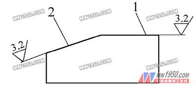
(1) The difference in the shape of the machined surface requires the division processing. As shown in Fig. 2, the workpiece is divided into two parts, 1 and 2. If it is not processed in separate areas, it will affect the processing efficiency and the surface quality is not high. If part 1 is machined with a face milling cutter, the machining of the 2 part with a ball milling cutter will better meet the workpiece requirements.

figure 2
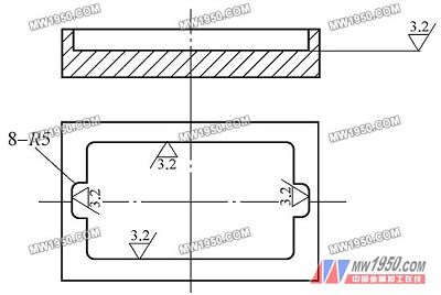
(2) Different machining areas have different dimensional differences. Partition processing is required. For example, for a wide cavity, a larger tool can be used to increase the machining efficiency. For smaller cavities or corners, it is necessary to select a suitable tool for machining. . As shown in Figure 3, the cavity is first machined with a Φ40mm end mill, and the 8-R5mm round corner is re-machined according to the trajectory of the Φ10mm end mill.

image 3
Next page
Ground Screw For Park And City Building
Using Honde Ground Screws requires no excavation or concrete pouring and leaves the landscape and vegetation untouched. They are easy to dismantle and relocate for temporary projects.
Solar lighting
Bollard lighting
Awnings and sunsails
Playground equipment
Walking trail lighting
Paintball courses and fences
Goal posts and field equipment
Park and sports field lighting
Park and event structures
Screw in Ground Anchors,Building Deck with Ground Screws,Ground Anchors for Retaining Walls
Hebei Honde Plastic & Metal Co., Ltd. , https://www.foundation-system.com