Figure III

Figure 4
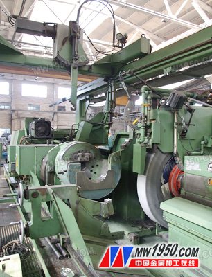
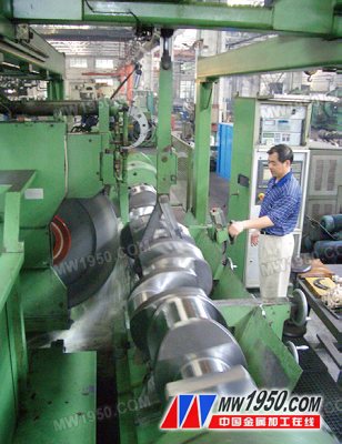
With the development of numerical control technology and the improvement of the functional level of machine tools, a new equipment and new process for grinding and grinding the crankshaft has been developed abroad. It can grind the crankshaft at the same time by clamping once on the same machine. The main journal and the connecting rod neck do not need to use two pieces of equipment to grind the crankshaft main journal and the connecting rod neck in turn.

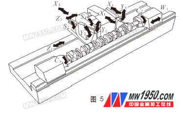
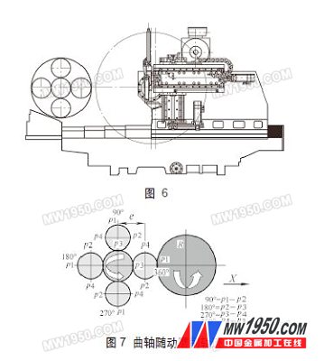
Figure 5 is a schematic illustration of the basic structure and processing arrangement of the apparatus. The device is designed as a control mode of full CNC control and full-closed feedback measurement on the electrical system. It breaks the structural distribution of the traditional grinding machine in mechanical design, and changes the movement of the original headstock and the workpiece Z axis to the movement of the wheel frame and the head and tailstock. The workpiece is fixed and the bed length can be designed to be shorter. Thanks to the X-axis transverse slide principle, many factors such as machine tool deformation caused by the movement of the workpiece can be overcome and eliminated, and the rigidity of the machine tool is also enhanced. The table top for fixing the workpiece is designed to be inclined by 20° to the direction of the wheel frame, so that the coolant can be easily drained to remove a large amount of grinding particles, ensuring the thermal stability of the machine tool and the workpiece is tilted by the worktable by 20°. The tailstock can be safely clamped on the work surface of the fixed workpiece. Due to the difference in design structure, the grinding method is also different from the conventional conventional crankshaft grinding machine. The spindle neck grinding adopts the plunge grinding method, and the connecting rod neck grinding adopts the plunge-type follow-up grinding method. 6 and 7 are schematic diagrams of the trajectory of the crankshaft and the grinding wheel in the follow-up grinding method.

The formula of the follow-up grinding method:

Where X - wheel frame transverse slide table moving axis; C - head and tail block workpiece clamping rotation axis.
The use of follow-up grinding is a relatively advanced processing method, but it has higher requirements for equipment, especially the relationship between hardware and software. The follow-up grinding method actually involves the relationship between the rotational position of the crankshaft and the linear motion of the grinding wheel frame. The key points are:
(1) C 1, C 2 and X 1 must be kept in sync. That is, the headstock C 1 and the tailstock C 2 clamp the two ends of the crankshaft, eccentric to the center line of the connecting rod neck of the main journal, the trajectory around the axis of rotation of C 1 , C 2 , and the straight line of the slide of the X 1 axis wheel carrier The distance relationship between the movement of the front and rear movements is always such that the outer diameter of the connecting rod neck is kept tangent to the outer circumference of the grinding wheel at any angle of 360°.
(2) The accuracy of the mechanical transmission chain, the accuracy of the grating feedback system, and the accuracy of the online measurement system.
(3) The development of the follow-up grinding application software is reasonable and practical.
Previous Next
stainless steel, sink strainer,fruit vegetable washing drain basket,kitchen tool,draining rack, draining basket.
Shenzhen Lanejoy Technology Co.,LTD , https://www.szlanejoy.com