Traditional EDM is mainly divided into two categories: EDM (SEDM) and Wire EDM (WEDM). One of the key points in molding processing is the fabrication of shaped electrodes. Tools are designed and manufactured to account for almost half of the total processing time and cost. For many years, electrical processing researchers have been looking for alternatives to shaped electrodes. EDM-Mill uses a simple shape electrode to make a forming motion in a certain trajectory, and processes it through the discharge between the tool electrode and the workpiece. This avoids the fabrication of the formed electrode and improves productivity. Correspondingly, it also puts higher requirements on EDM machines and needs to develop a special CNC system. AutoCAD is currently the most widely used CAD software.
It not only has rich 2D drawing, editing commands and strong 3D modeling capabilities. Moreover, programming methods such as a line-shaped file, a menu file, and a command file are provided. Its flexibility and openness have determined that many applications choose it as a supporting platform for graphic design, editing, and post-processing. AutoCAD and its graphical format have become a de facto international industry standard. In addition, AutoCAD can exchange data with other CAD systems or CAM systems through standard data formats. This is called "DrawingeXchangeFile", referred to as DXF file. To achieve CAD/CAM integration in EDM, it is necessary to extract useful part information from this file and convert this information into a CNC program for EDM machines.
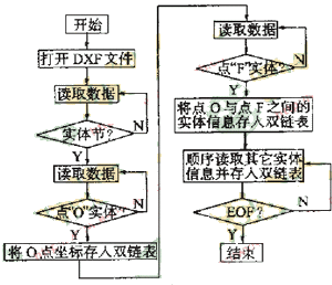
1 interface program designA DXF file is an ASCII text file. A typical DXF file consists of six sections: a title section, a class section, a table section, a block section, a solid section, and an object section. DXF files contain a lot of information, but useful for NC programming is the physical section. Therefore, we only care about the content of the entity section. According to the data format of the entity section, the corresponding interface program is compiled, and the geometric information of the graphic can be extracted. However, the starting point coordinates obtained from the DXF file are the starting points of the first input graphic. The setting of the starting point of EDM milling needs to consider the stress state of the workpiece and the influence on the machining accuracy and surface roughness of the workpiece. Often it is inconsistent with the starting point of the drawing. To solve this problem, we add the character "O" next to the processing start point when drawing the graph. To facilitate modification and reordering of entities in DXF files. We use a double-linked list structure to store the physical coordinate values.
| |
|
|
| Figure 2 side profile | |
2 Automatic discrimination of machining direction
Once the part geometry is obtained, the tool path can be generated by compensating the tool radius (cylindrical tool). When tool radius compensation is performed, the offset direction of the tool center is determined by the inner and outer contour characteristics and the machining direction (the rotation direction of the machining closed loop). The internal and external characteristics of the contour are set during machining, and the machining direction must be determined according to the contour map and tool feed direction. Therefore, the discrimination of the machining direction is the basis for solving the tool compensation. The outline of the part is generally composed of straight lines and arcs, so we discuss the calculation of the plane outline tool trajectory composed of these two figures.
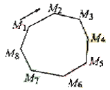
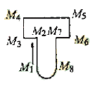
The sides of the polygon are treated as vectors, the vector direction is the direction of the pass, and the vectors are sequentially connected in the order of the pass. M 1 M 2 , ..., M 7 M 8 , M 8 M 1 in Fig. 1 . The arc profile takes the line between the start and end points. The arrows in the figure indicate the direction of the tool. For the graph shown in Fig. 2(a), the points are all bumps, and the discriminating method is relatively simple. The rotation direction of the machining closed loop can be determined by judging the cross product of two vectors adjacent to any vertex. It is specified that the machining closed-loop counterclockwise rotation is positive and the clockwise rotation is negative. Then, when the cross product of the two vectors is positive, the machining direction runs counterclockwise: the opposite direction is clockwise. But for the outline shown in Figure 2(b), this method will not work. We have designed the following two methods of discrimination.
Next page
Tile Cutting Tools,Simple Ceramic Cutter,Simple Porcelain Cutter,Mannual Ceramic Tile Cutter
NINGBO SANDING EDGE MECHATRONICS INDUSTRY AND TRADE CO., LTD , https://www.sandingedge.com


