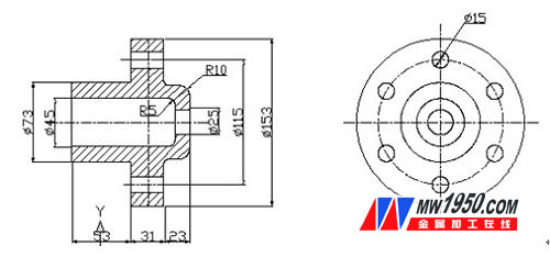
First, let's look at a simple drawing (Figure 1). This drawing can be judged as a CAD drawing of a part, consisting of a shaft type part and a flange type part. So how is this part drawing drawn? Below, we will use the Haochen CAD Machinery 2011 software to demonstrate the drawing process for everyone.

figure 1
To draw this figure, we need to carry out a simple structural analysis: we can see that the center of the part has a hole in the center and a chamfer on the outer circle, so you can use the [shaft part design] in Haochen CAD mechanical software. The function quickly draws the main view, and then the Haochen CAD mechanical software [Accessibility] - [Create View] command to quickly generate the left view from the main view - this is also our idea of ​​drawing graphics.
Drawing steps:
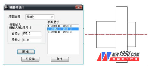
1. First, we open Haochen CAD mechanical software, click [Haochen Machinery] - [Mechanical Design] - [Axis Design], and use the shaft design function to design the approximate contour of the shaft (Figure 2). .

figure 2
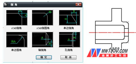
2. Next, we draw the hole in the center and perform the corresponding chamfering on the contour. Among them, when chamfering, you can use the [National Standard Chamfer] command in Haochen CAD mechanical software, which is more convenient and faster (Figure 3).

image 3
BOGO HARDWARE & FITTING CO.,LTD , https://www.bogo-hardware.com