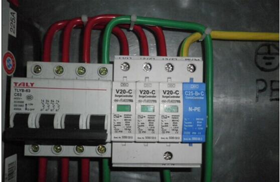
As a pressure-limiting product, the V20-C is equipped with a high-energy zinc oxide varistor, which has better nonlinear characteristics. The module has the advantages of short response time, low residual voltage, large current capacity, long life, and no freewheeling.
If the varistor deteriorates due to overload, the built-in circuit breaker will interrupt the connection to the power supply and the color of the fault display window will change from green to red. Remote remote signaling device (OBOV20-C/FS) with remote voltage monitoring device. The arrester can be safely hot-swapped without interruption.
V20-C pressure sensitive lightning arrester application OBOV20-C is designed to protect the low voltage load equipment below 1000V according to the standard according to the VDE-0675 standard. It protects electrical equipment from transient overvoltage damage caused by lightning and switching operations. Depending on the type of power input, there are several models to choose from.
V20-C Pressure-Sensitive Lightning Protector Specially Configured After adopting the special light control system LCS of OBO, remote monitoring of each OBOV20-C becomes easy. In addition, the V20-C is also equipped with an audible and visual alarm device (OBOV20-C/AS) and a long-distance remote signaling device (OBOV20-C/FS) with a remote voltage monitoring device. The arrester can be safely hot-swapped without interruption.
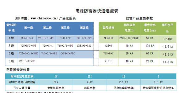
OBO lightning protection device selection table

V20-C pressure-sensitive lightning protection device technical parameters
model
OBO V20-C/0
V20-C/0-VA
Nominal operating voltage Un
75V~
230V~
385V~*
230V~*
Maximum withstand voltage U~max
U-max
75V~
100V-
275V~
350V-
385V~
505V-
280V~
-
Classified according to VDE0675, Part6
Class C
Normal discharge current limit In(8/20)
15KA
Maximum test discharge current Imax (8/20)
40KA
30KA
Test residual pressure upper limit Ures Is=1KA
240V
0.8 KV
1.2 KV
<1.4KV
Is=5KA
300V
1.0 KV
1.4 KV
Is=10KA
350V
1.2 KV
1.7 KV
Is=15KA
400V
1.3 KV
1.8 KV
Is=40KA
550V
1.9 KV
2.3 KV
Combination Module Maximum Discharge Current (8/20) Single Module
40 KA
40 KA
40 KA
30 KA
Dual module
75 KA
75 KA
75 KA
30 KA
Three modules
100 KA
100 KA
100 KA
30 KA
Four modules
100 KA
100 KA
100 KA
30 KA
Continuous discharge current IsL (2000us)
200A
Reaction time tA
<25ns
<100ns
Affordable fuse specifications with a short circuit current of 25KA
100AgL
Connection line diameter selection
2.5-35mm2 (single or stranded copper wire)
fixed
35mm wide guide rails, according to DIN EN 5002
colour
gray
green
material
Polyimide
range of working temperature
-40°C to +80°C
Dimensions according to DIN 43880
Single module
Dual module
Three modules
Four modules
Width 17.8mm deep 55mm
Width 35.5mm deep 55mm
53.4mm deep and 55mm deep
71.2mm deep and 55mm deep
Models marked with * are more suitable for use in TT or IT systems.
Operating temperature range
-40°C-----+80°C
V20-C/3+NPE/AS Technical Description Application OBOV20-C/3+NPE/AS is designed according to IEC61312, IEC61643, VDE0675 and is used in Class C lightning protection. The overvoltage protector is especially suitable for TT and IT grid situation. The new OBOV20-C/3+NPE/AS design meets the requirements of DINVDE 0100 Part 534/A1, making it easy to install the TT and IT grids. The OBOV20-C/3+NPE protects the user equipment from transient surges caused by lightning and switching operations.
V20-C/3+NPE module structure and dimension drawings.
Structure and Function Description OBOV20-C/3+NPE/AS type surge arresters use three zinc oxide varistor modules to limit the voltage between the phase and neutral lines to clamp the overvoltage to very low amplitudes. At the same time, the varistor releases a large discharge current in a very short response time (<25 ns). For neutral and ground protection, this model uses a high-energy gap discharge module to limit the overvoltage between neutral and ground, which is caused by long-term use in the power grid or after several transient over-voltages. When the aging condition of the lightning arrester occurs, the built-in dynamic and thermal circuit breaker inside the V20-C module will immediately move, and the lightning arrester will be safely separated from the main circuit. At the same time, the display window will change from green to green at the same time. red.
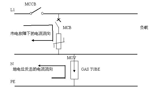
Because the V20-C/3+NPE/AS lightning arrester adopts a new structure, the front fuse (or air breaker) of the lightning arrester can be used when the surge protector is overloaded due to excessive power fluctuation or mains failure. Timely and safe action. So that the lightning protection device can be safely separated from the main circuit, to avoid short-circuit damage caused by the continuous opening of the lightning protection device. The specific protection principle is illustrated as follows:
From the above figure, we can see that due to the use of the highest continuous operating voltage between the phase line and the zero line is 385V varistor module, so that the SPD can adapt to the power environment with large fluctuation range. Because a high-energy graphite is used between the neutral line and the ground line, even under the normal lightning state, the working voltage of the phase line and the neutral line exceeds 385V, due to the impedance between the phase line and the neutral line. Small, the fault current is enough to make the front stage 32A open and open, so that the lightning protection device operates safely.
From the above figure, the new structure of the SPD will also play a role in the counterattack caused by the ground potential. When the potential causes a counterattack between PE and N after the lightning enters the ground, the counterattack current passes through the high-energy graphite after the PE and N. Between the conduction, and through the formation of a loop after the remote neutral point, so that the counterattack current without the phase line, power equipment damage.
NPE module technical parameters
Nominal response voltage (DC)
UagN
500V±20%
Discharge tube standard operating voltage
Ur
250V to 50/60Hz
Insulation resistance (under 100V)
Riso
>10Gohm
Lightning test current (10/350) acc.IEC529
Peak current
Is max.
10kA
Charge amount
Q
5As
Unit energy
W/R
25.7KJ/Ω
Nominal discharge current
isN(8/20)
50kA
Voltage at a voltage waveform of (1.2/50) operating voltage in a lightning surge
UAs100
≤1kV
Protection level
≤1kV
Response time
tA
≤100ns
range of working temperature
-40°C to +80°C
Basic requirements for V20-C pressure-sensitive surge protectors 1. Installation location: The V20-C should be installed on the AC input side of the switch power cabinet in the equipment room. It should be connected in parallel with the outgoing side of the main circuit breaker.
2. The length of the connecting wire between the lightning arrester and the power supply system should be less than 50cm. The length of the lightning arrester and the ground wire should also be less than 50cm.
3, the choice of wire cross-section (according to VDE0100 standard) Unit: mm2
Distribution power line
≤35
50
≥70
Connecting wire
10
16
25
Ground wire
≥16
25
≥35
4. Due to the characteristics of V20-C/3+NPE/FS, it is recommended to connect a reserve air breaker in series before the SPD. It is recommended that the capacity of the air breaker be 32A, and Class A air breaker (eg Siemens5sx2332-5).
5, FS wiring installation There are three wiring ports, of which 1-2 terminals are normally closed contacts, 1-3 are normally closed contacts, depending on the user's alarm device, connect different terminals.

Note: It is not possible to route protected lines in parallel with unprotected lines or ground lines.
Remote alarm connection diagram
Dc Axial Fan 92X92X38,Dc Fans Cooling,Dc Axial Cooling Fans,Machinery Exhaust Cooling Fan
Crown Electronics CO., LTD , https://www.crownelectronicstw.com